| Basic Radio is a free introductory textbook on electronics based on tubes. See the editorial for more information.... |

|

Home  Basic Circuits Basic Circuits  The Operation of Oscilloscopes The Operation of Oscilloscopes  Lissajou Patterns Lissajou Patterns |
||||||||||||||||


|
||||||||||||||||
|
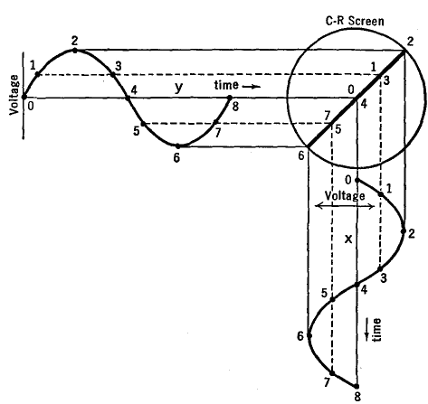
Lissajou PatternsAuthor: J.B. Hoag Let a sinusoidal alternating voltage be applied to the horizontal deflecting plates alone. A single horizontal line will be seen on the screen. The beam, starting at the left of the screen, moves slowly at first, then rapidly across the center, and slows down to stop at the right of the screen, after which it reverses its direction, again traveling slowly at the ends and rapidly in the center. But to the eye, only a single straight line appears. If, next, an alternating potential is applied to the vertical deflecting plates alone, then a similar vertical line will appear on the screen. We now consider the patterns which will appear on the screen when alternating voltages are applied simultaneously to both the X and the Y deflecting plates. First of all, let us assume that the alternating voltages have precisely the same frequency and are in the same phase; in other words, they both pass through their zero values at the same moment and they both reach their crests at the same moment.
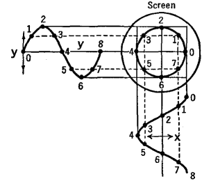
Let us next consider the case when the two voltages have exactly the same frequency and amplitude but start a quarter of a period out of phase with respect to each other. The application of these two voltages to the X and Y plates results in a movement of the spot of light on the screen in a circular pattern as shown in Fig. 22 Q. If the two voltages are not of equal amplitude, an ellipse will be formed on the screen.
Next, let us consider the case when the voltages on the X and Y plates are of equal amounts, start in phase with each other, but differ in frequency in the ratio of 2 to 1.
Figure 22 R shows how the figure 8 pattern observed on the screen is compounded from these two " simple harmonic " motions. It is an interesting problem to work out the shapes of the pattern on the screen when alternating potentials of different amplitude ratios, frequency ratios, and phase differences are applied to the deflecting plates.
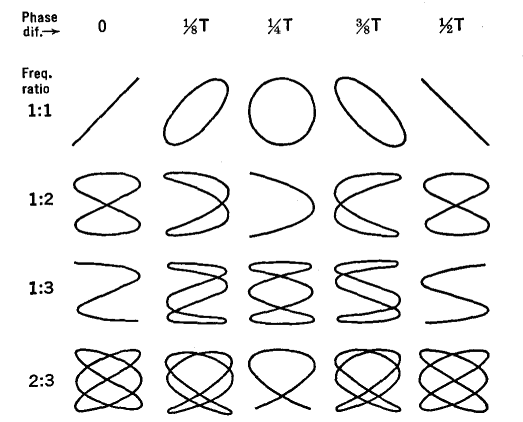
Figure 22 S illustrates a few of the possibilities. Conversely, when a particular pattern is noted on the screen, Fig. 22 S permits one to tell the frequency, amplitude, and phase relationship of an unknown voltage with respect to a standard. The various figures shown are known as Lissajou patterns. A phase-splitting circuit, used for obtaining elliptical or circular patterns, is shown in Fig. 22 T (see also Sec. 19.6). One set of plates is connected across resistance R. The other deflecting plates are connected across condenser C. The voltage across R will always be in phase with the input voltage, whereas the voltage across C will always be 90° ahead of the applied voltage. If R is adjusted so that its resistance is numerically equal to the reactance of C, a circular pattern will appear on the screen. If the resistance and reactance of R and C are not equal to each other, an elliptical pattern will be obtained. Furthermore, an alternating current of unknown frequency may be applied in series with r, as shown in Fig. 22 T.
Then patterns such as those of Fig. 22 U will appear on the screen.
By counting the number of peaks in these patterns, one has a direct measure of the ratio of the unknown frequency to that of the standard input frequency. This is particularly valuable when the frequencies differ from each other by comparatively large amounts. Unless these frequencies are exact multiples of each other, the pattern will appear to rotate. The speed of rotation is a measure of the lack of exact integral-frequency ratio. Having established a circular pattern on the screen by means of the circuit of Fig. 22 T, it now becomes possible to produce a spiral pattern. In order to do so, the sliding contact on resistance R1 is moved rapidly from one end of the rheostat to the other. This changes the radius of the circle in proportion to the amount of voltage tapped off of R1. Elaborate electronic circuits can be devised which are equivalent to this variable applied voltage. If an unknown but comparatively small voltage is connected in series with the a.c. input voltage of Fig. 22 T, the deflecting voltages on the X and Y plates will be proportionally increased and decreased, with the result that the circular pattern becomes crenellated into a pattern such as that shown in Fig. 22 V.
Also, short time pulses such as those from the static discharges in storms or those from man-made machines can be similarly injected, to cause momentary deviations from the circular pattern. In this way, a comparatively long time axis, the circumference of the circle, can be obtained on a small sized screen.
|
||||||||||||||||
Home  Basic Circuits Basic Circuits  The Operation of Oscilloscopes The Operation of Oscilloscopes  Lissajou Patterns Lissajou Patterns |
||||||||||||||||
Last Update: 2009-11-01


