| Basic Radio is a free introductory textbook on electronics based on tubes. See the editorial for more information.... |

|

Home  Basic Circuits Basic Circuits  Operation of Gas-Filled Tubes Operation of Gas-Filled Tubes  Phase Shifters Phase Shifters |
||||||||||


|
||||||||||
|
Phase ShiftersAuthor: J.B. Hoag
In Fig. 19 H, the current from the generator divides along the two paths r and RC. In path r, the voltage and current are in phase. In path RC, the current leads the generator voltage by something between 0° and 90°. Thus the voltage at point 4 reaches its peak value ahead of that at point 2. If R is large, this "phase difference" between 4 and 2 will be small, whereas if C is large it will be appreciable. A phase shifter using an inductance and a resistance is shown in Fig. 19 I.
By changing L and/or R, the phase difference between the current and voltage through the load can be changed.
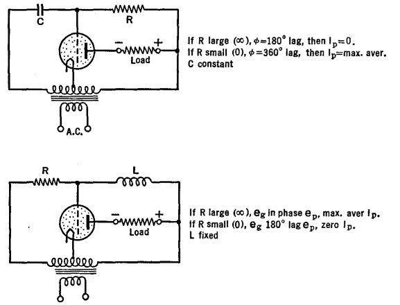
Figure 19 J shows a bridge-type phase shifter where adjustments of the resistances and condensers permit of changing the output phase from 0° to 180° with respect to the input. Reversing the leads of either the input or the output gives phase changes from 180° to 360°. Figure 19 K shows practical circuits for the phase control of gas-filled tubes.
|
||||||||||
Home  Basic Circuits Basic Circuits  Operation of Gas-Filled Tubes Operation of Gas-Filled Tubes  Phase Shifters Phase Shifters |
||||||||||
Last Update: 2009-11-01


