| Electrical Communication is a free textbook on the basics of communication technology. See the editorial for more information.... |

|

Home  Electric Networks Electric Networks  Filters Filters  High-Pass Filter High-Pass Filter |
|||||


|
|||||
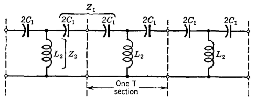
High-Pass FilterSuch a network freely passes all signals above a certain critical or cutoff frequency and greatly attenuates signals below this frequency. Three T sections of a constant-k high-pass filter are shown in Fig. 32. In the high-pass filter Z1 = 1/(jωC1), since the condensers 2C1 are in series, Z2 = jωL2, and the ratio of these two impedances is Z1/Z2 = -1/(ω2L2C1). From the general filter theory, the frequency
band passed will lie between Z1/Z2 = 0 and Z1/Z2 = -4. When the first value is substituted, Z1/Z2 = -l/(ω2C1L2) = 0, and fc" will be infinite. When the second substitution is made, then -l/ω2L2C1) = -4, and
Thus, the high-pass filter of Fig. 32 will freely pass all frequencies between fc' and infinity and will greatly attenuate all frequencies below fc'. The iterative impedance equations for the T section of Fig. 32 are found in the same general manner as for the low-pass filter. From equation 45,
In a similar manner the iterative impedance for a π section is found from equation 46 to be
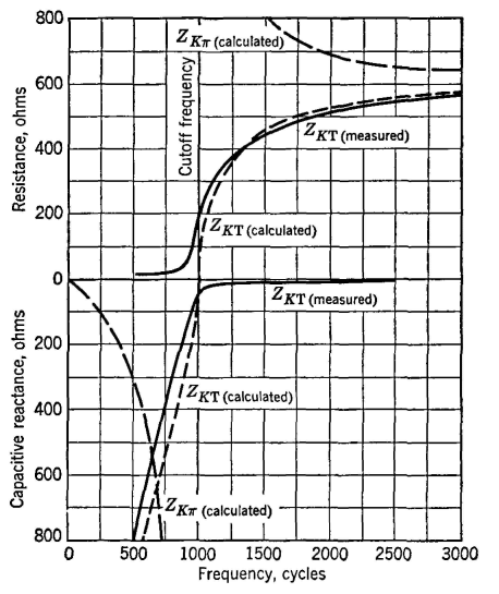
As equations 79 and 80 indicate, ZK varies with frequency in both the T and the π sections (see also Fig. 33). For both types of sections, ZK = sqrt(L2/C1) at f = ∞. For the T section, ZKT = 0 at the cutoff frequency; and for the π section, ZKπ = ∞ at the cutoff frequency.
The iterative impedance used for high-pass filter design is at f = ∞; hence, for both the T and the π sections,
The design formulas are now easily found. Since ZK = sqrt(/L2/C1), l/(ω2L2C1) = 4, and L2/C1 = 4ωc2L22, then ZK2 = 4(ωc2L22, and therefore
The value of C1 can now be readily found as follows
To consider a typical case, suppose that it is desired to design a high-pass filter to operate between circuits of 600 ohms impedance, and to cut off at 1000 cycles. Then, L2 = 600/(4 x 3.1416 x 1000) = 0.0477 henry, and C1 = 1/(4 x 3.1416 x 1000 x 600) = 0.000000132 farad or 0.132 microfarad. If ZK were desired, and L2 and C1 had been given, then ZK = sqrt(L2/C1) = sqrt(0.0477/0.000000132) = 600 ohms, approximately. As shown in Fig. 32, two capacitors of 2C1 and an inductor L2 would be used for a T section. For a (π section, two inductors of 2L2 and one capacitor of C1 would be used. The attenuation of a constant-k high-pass filter can be calculated from equation 67. Thus,
when the value given by equation 82 is substituted for L2, and the value given by equation 83 is substituted for C1. At 500 cycles, for the high-pass filter under consideration, α = 2 cosh-1 (1000/500) = 2 cosh-1 2, and (α = 2 x 1.31 = 2.62 nepers, or 2.62 x 8.686 = 22.8 decibels. The dotted curve of Fig. 34 shows calculated values of attenuation for the filter under consideration (assumed to be composed of lossless elements), and the solid curve shows the attenuation measured on an actual filter, designed as explained in the preceding paragraph. The phase shift of a constant-k high-pass filter can be found from equation 63
when the same substitutions as in equation 84 are made. For the filter under consideration, and at a frequency of 2000 cycles, (β = 2 sin-1(1000/2000) = 2 sin-1 0.5 = 60°. The dotted curve of Fig. 35 shows calculated values, and the solid curve shows values measured with a cathode-ray oscilloscope. As for the low-pass filter, an analysis of the characteristics of a high-pass filter can be made from simple reactance sketches as in Fig. 36. In this figure Z1 = l/(2πfC1) and Z2 = 2πfL2, giving the curves positions different from Fig. 31. Transmission will occur for such frequencies that Z1 lies between -4Z2 and the frequency axis as indicated.
|
|||||
Home  Electric Networks Electric Networks  Filters Filters  High-Pass Filter High-Pass Filter |
|||||
Last Update: 2011-05-30


