| Electrical Communication is a free textbook on the basics of communication technology. See the editorial for more information.... |

|

Home  Electroacoustic Devices Electroacoustic Devices  Receiver Characteristics with Diaphragm Free Receiver Characteristics with Diaphragm Free |
|||||||||||||||


|
|||||||||||||||
Receiver Characteristics with Diaphragm FreeThe impedance characteristics with the diaphragm blocked are similar to those of a coil on an iron core containing an air gap. With the diaphragm free, however, the motional impedance and the mechanical resonance of the diaphragm greatly change the impedance characteristics.
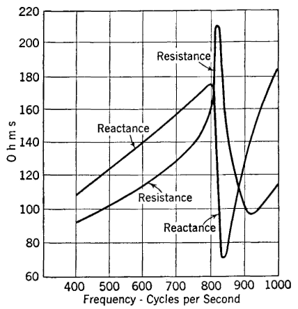
The receiver diaphragm has a certain mass which through its inertia effect tends to prevent changes in diaphragm motion. This causes an effect analogous to inductive reactance. The diaphragm is of elastic material and thus possesses compliance (displacement per unit force or reciprocal of stiffness1) which causes an effect analogous to capacitive reactance. At certain frequencies these two mechanical reactances neutralize each other, and mechanical resonance of the diaphragm occurs. When mechanical resonance is reached, the motion of the diaphragm is greatest and is in phase with the impelling force. Since the greatest motion means the greatest flux change, the largest value of back voltage will be induced in the receiver windings and thus the motional impedance will be greatest at this point (Fig. 30). The manner in which the total impedance changes with frequency is evident from Fig. 31. These curves show that at the resonant point the reactive component becomes very small and the resistive component becomes large, indicating that the diaphragm motion is in phase with the impressed electrical impulses.
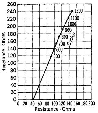
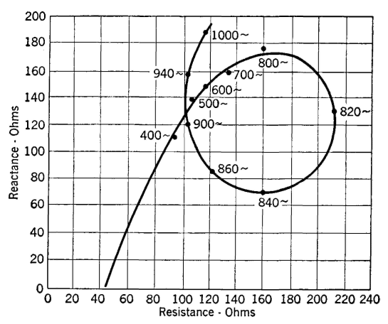
When the resistance and reactance components measured with the diaphragm free are plotted, the interesting curve of Fig. 32 (corresponding to Fig. 29) is obtained. Since Figs 29 and 32 are for the same receiver, they may be plotted together as in Fig. 33. The vector difference between corresponding points on these two curves as shown in Fig. 33 is the motional impedance.
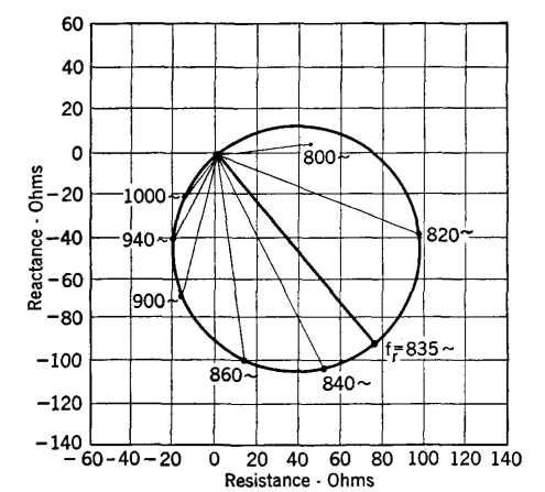
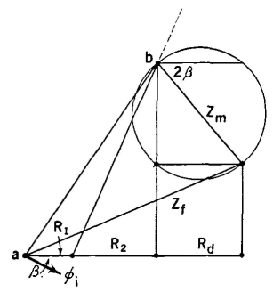
If each of these motional impedance lines is plotted from a common point the curve of Fig. 34 will be produced. As is shown, the length of the motional impedance line at the resonant frequency fr determines the diameter of the circle. The vector diagram of a telephone receiver with the diaphragm free can now be drawn. As Fig. 35 indicates, this diagram is produced by adding the motional impedance circle of Fig. 34 to the impedance diagram of Fig. 27. This figure represents conditions at the resonant frequency, the line Zf being the total measured impedance at this frequency. As the test frequency is varied the total impedance Zf intersects the motional impedance circle at different points, and also the point 6 moves along the curve of Fig. 29. Thus, the curve of Fig. 32 is produced.
As indicated in Fig. 35 the motional impedance Zm at the resonant frequency lags behind a line parallel to the X axis by the angle 2β, that is, by an angle twice as great as that by which the receiver flux in Fig. 27 lags the current through the receiver windings. This can be explained by an analysis of receiver action.33 Although the discussion given in the preceding pages was for the old-type telephone receivers, which are highly resonant, attention again is called to the fact that the general theory applies also to the new-type receivers and to certain loudspeakers. Impedance tests made on moving-coil loudspeakers with the diaphragm blocked, and free, and with and without the horn attached, and with different types of horns, provide interesting and useful data. Such tests can be performed by driving the motor element with a good amplifier, and by measuring the current and voltage with thermocouples and vacuum-tube voltmeters, and the phase angle with a cathode-ray oscilloscope.
|
|||||||||||||||
Home  Electroacoustic Devices Electroacoustic Devices  Receiver Characteristics with Diaphragm Free Receiver Characteristics with Diaphragm Free |
|||||||||||||||
Last Update: 2011-05-18


