|
Monostable Operation
Author: Leonard Krugman
 
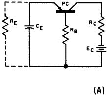
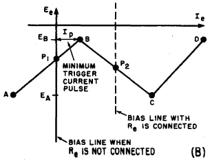
Fig. 6-21. (A) Basic monostable trigger circuit. (B) Idealized characteristic.
The basic monostable circuit is illustrated in Fig. 6-21 (A). The only difference between this circuit and the emitter-controlled relaxation oscillator illustrated in Fig. 6-17 (A) is the elimination of the emitter resistor RE. Since this action removes the d-c emitter current bias (IE = 0), the operating point shifts from the negative-resistance region (P2) to the point intersection of the voltage axes at IE = 0(Pj). This change is illustrated in Fig. 6-21 (B). The circuit is no longer capable of self-sustained oscillation since it is biased in the stable cut-off region. Now, if a pulse of sufficient magnitude (at least equal to IP) is applied to the emitter, operation is forced into the regenerative region. The current jumps to its value at point D, and the negative charge on the emitter condenser starts to build up. When the charging current is reduced to its value at point C, operation again enters the regenerative region, and the current is quickly reduced to its value at A. The charge on the condenser gradually leaks off through the emitter base circuit (re + rb + RB) until the stable operating point Pj is reached. The circuit is now ready for another trigger pulse.
The emitter resistance is very high in the cut-off region due to the reverse bias. As a result, the same constant CE (re + rb + RB) is large compared to that of the relaxation type illustrated in Fig. 6-17 (A). This is the major factor limiting the repetition rate of the trigger pulse if sensitive operation is required.
|


 Transistor Oscillators
  Trigger Circuits
  Monostable Operation


 Transistor Oscillators
  Trigger Circuits
  Monostable Operation


