| Transistor Basics is a free introductory textbook on transistors and their basic applications. See the editorial for more information.... |

|
Home  Grounded Emitter and Grounded Collector Transistors The Grounded Collector Connection Reverse Power Gain Grounded Emitter and Grounded Collector Transistors The Grounded Collector Connection Reverse Power Gain |
||


|
  |
|
|
Reverse Power Gain in the Grounded Collector CircuitAuthor: Leonard Krugman
Fig. 4-15. Equivalent "T" for reverse operation of grounded collector connection. A.
B.
C.
D.
Therefore, it can be seen that any of the equations derived for operation in the forward direction can be revised for use in the reverse direction by substituting r11 for r22, r12 for r21, r21 for r12, and r22 for r11. For example, the maximum available power gain in the forward direction,
|
||
| Home Grounded Emitter and Grounded Collector Transistors The Grounded Collector Connection Reverse Power Gain |
|
|

 ,
,  ; which is
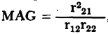 , becomes
  in the reverse direction.
Last Update: 2010-11-17