| Transistor Basics is a free introductory textbook on transistors and their basic applications. See the editorial for more information.... |

|

Home  Transistors and Their Operation Transistors and Their Operation  The PN Junction Photocell The PN Junction Photocell |
||
| See also: Intrinsic Germanium | ||


|
||
|
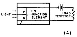
The PN Junction PhotocellAuthor: Leonard Krugman Figure 2-9 (A) illustrates the essential construction and connections for the P-N junction photocell. The photocell is connected in series with a battery and a load resistor. The cell is biased by the battery in the reverse direction. Under these conditions, and with no light striking the P-N junction, approximately ten microamperes of current flow. The current value is low at this time because of the high resistance of the junction. However, when light strikes the P-N junction, the load current increases at a rate proportional to the light intensity.
Fig. 2-9. (A) P-N junction photocell construction. (B) Typical junction photocell operating curves.
Basically, light from any source is composed of tiny particles of energy called photons. Thus, when light strikes the P-N junction element, in effect photons are bombarding the surface of the element and their energy is being absorbed by the germanium. The total energy absorbed is sufficient to disrupt some of the covalent bonds in the element, thereby creating free electrons and holes in the germanium, and increasing the number of available current carriers. When the light is removed, the current decreases rapidly because of the recombination of holes and electrons.
|
||
Home  Transistors and Their Operation Transistors and Their Operation  The PN Junction Photocell The PN Junction Photocell |
||
Last Update: 2010-11-17


