| Radio Antenna Engineering is a free introductory textbook on radio antennas and their applications. See the editorial for more information.... |

|

Home  High-frequency Antennas High-frequency Antennas  Horizontal Rhombic Antenna Horizontal Rhombic Antenna  Rhombic Antenna Arrays Rhombic Antenna Arrays |
|||||||||||||||||||||||||||||||||||||||||||||||||||||||||||||||||||||||||||||||||||||||||||||||||||||||||||||||||||||||||||||


|
|||||||||||||||||||||||||||||||||||||||||||||||||||||||||||||||||||||||||||||||||||||||||||||||||||||||||||||||||||||||||||||
|
Rhombic Antenna ArraysAuthor: Edmund A. Laport
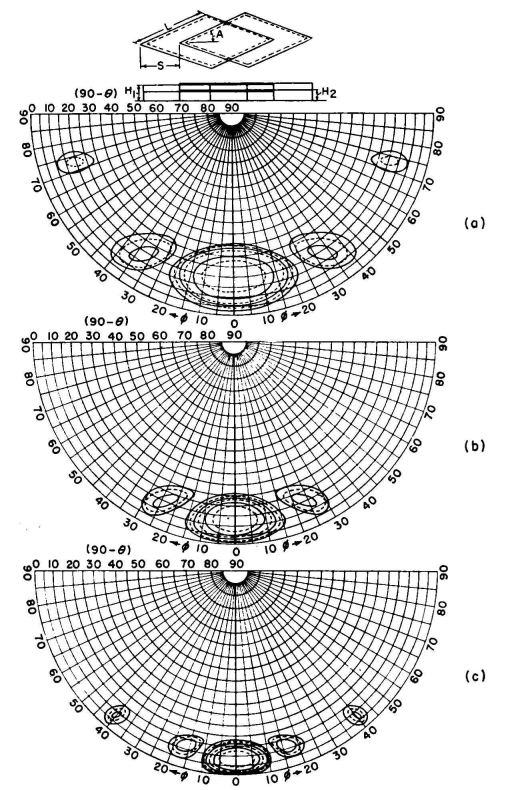
When azimuthal swing of signals is a disturbing factor, two such arrays can be used in diversity, by turning the axis of the second array off the great-circle bearing by an angle equal to that between the first null and the peak of the main beam. When two such antennas are spaced as in typical space-diversity operation and oriented in this manner, the maxi-mums of one rhombic pattern will fill the minimums of the other. To obtain this benefit, each rhombic must be associated with its own receiver and their outputs combined in diversity. This form of utilization is obviously a special application to avoid the effects of arriving signals that deviate from the great-circle bearing by an amount which exceeds half the beam width of the main lobe. Figure 3.89 shows the construction for a two-layer rhombic system having two wires per side in each layer. Figures 3.90 and 3.91 show what is possible by using arrays of these two-layer rhombic systems.
These figures, together with Figs. 3.78 and 3.88, represent optimum-design parameters for a frequency range of 2.25 to 1, based on idealized conditions. Comparison measurements on rhombic antennas of the types having the patterns of Figs. 3.78 and 3.88 are listed in Table 3.3, as published by Christiansen.
|
|||||||||||||||||||||||||||||||||||||||||||||||||||||||||||||||||||||||||||||||||||||||||||||||||||||||||||||||||||||||||||||
Home  High-frequency Antennas High-frequency Antennas  Horizontal Rhombic Antenna Horizontal Rhombic Antenna  Rhombic Antenna Arrays Rhombic Antenna Arrays |
|||||||||||||||||||||||||||||||||||||||||||||||||||||||||||||||||||||||||||||||||||||||||||||||||||||||||||||||||||||||||||||
Last Update: 2011-03-19


