| Radio Antenna Engineering is a free introductory textbook on radio antennas and their applications. See the editorial for more information.... |

|

Home  Medium-frequency Broadcast Antennas Medium-frequency Broadcast Antennas  Input Impedance in a Directive Array Input Impedance in a Directive Array  Phase Diagrams Phase Diagrams |
||||||||


|
||||||||
|
Phase DiagramsAuthor: Edmund A. Laport
In the phase diagram for this problem (Fig. 2.25), I2 is taken as reference phase, I1 will lag by 45 degrees, and I3 will lead by 45 degrees. The phase shift across A was found to be 77.5 degrees, the current I2 leading the main line current I0 by this amount. This brings I0 at -77.5 degrees in the diagram. Next the phase lag in the secondary lines is shown with reference to I0, so that the 135-degree line and A together total -212.5 degrees. An auxiliary vector is drawn for this.
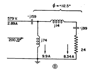
It is seen that the smallest angle between this auxiliary vector and I1 is counterclockwise, the direction of advance of phase. The angle is 167.5 degrees. Network B has been computed to have an advance of 55 degrees, leaving a phase advance of 112.5 degrees to be obtained in network D. For the last branch of the circuit, it is noted that the angle between the auxiliary vector at 212.5 degrees and I3 is -102.5 degrees (clockwise). If C is an L network, its phase lag is 66 degrees, and the values are as shown in Fig. 2.28. This leaves a lag of 36.5 degrees for network E.
After completing the synthesis of network E we have the circuits and values shown in Fig. 2.30. Now we note that networks A, B, and C all have a parallel reactance directly across the main line. Thus, their combined parallel value can be obtained by using one reactance instead of three. There are values of j87, -j536, and j425 in parallel, which is equivalent to j83.5 ohms. Combining all the circuits for the system, we have the diagram of Fig. 2.31. See Chap. 5 for a simple method of network synthesis for problems of this type.
|
||||||||
Home  Medium-frequency Broadcast Antennas Medium-frequency Broadcast Antennas  Input Impedance in a Directive Array Input Impedance in a Directive Array  Phase Diagrams Phase Diagrams |
||||||||
Last Update: 2011-03-19


