| Capacitors, Magnetic Circuits, and Transformers is a free introductory textbook on the physics of capacitors, coils, and transformers. See the editorial for more information.... |

|

Home  The Transformer The Transformer  Induced EMFs Induced EMFs |
|||||||||||||||||||
| See also: Induced emf. - Lenz's Law, Magnetomotive Force, mmf | |||||||||||||||||||


|
|||||||||||||||||||
Induced EMFs
For its operation, the transformer depends on the emfs that are induced in its various circuits by a common magnetic flux. According to Faraday's Law, the emf induced in a fixed circuit is proportional to the time rate of change of the magnetic flux. If there are N turns of wire in series, through all of which the flux undergoes the same rate of change, the induced emf is
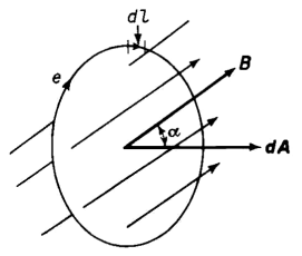
The minus sign is in accordance with Lenz's Law and shows that the induced emf e would produce a current in such a direction as to oppose any change in the flux Φ through the circuit. It is important to note that the opposition is to the change in the flux and not to the flux itself. The sense of the induced emf e in relation to an increasing flux through a closed path is shown in Fig. 6-1.
The vector dA in Fig. 6-1 represents an elemental area through which the flux density is represented by the vector B at the angle α to the normal of the surface associated with the area vector dA. If E is the magnitude of the electric field intensity due to the varying magnetic flux, then the emf around the closed path is
where E cos Θ is the component of the electric field intensity parallel to the path at a given point. This component of E has the same sense as e. If the integration in Eq. 6-2 is taken around the complete path once, the result is the emf per turn. This emf, however, exists whether the path is occupied by a conducting material or by free space or some other nonconducting material. Hence, we have from Eq. 6-1
as the volts per turn. The flux Φ which links the area A enclosed by the path in Fig. 6-1, is obtained by integrating the normal component of the flux density B over the area A so that
and
If the configuration of the path is fixed, the area A is constant, and only the quantity B cos α is free to change with time, thus permitting differentiation with respect to time under the integral, and
From Eqs. 6-1, 6-2, and 6-6 it follows that
which can be expressed in vector notation as
|
|||||||||||||||||||
Home  The Transformer The Transformer  Induced EMFs Induced EMFs |
|||||||||||||||||||
Last Update: 2011-02-16


