| Capacitors, Magnetic Circuits, and Transformers is a free introductory textbook on the physics of capacitors, coils, and transformers. See the editorial for more information.... |

|

Home  Magnetic Circuits Magnetic Circuits  Energy Product Energy Product |
|||||||||||||||


|
|||||||||||||||
Energy Product
The energy product for the magnet material operating at the point P is the product BH at that point. When a magnet supplies an air gap with flux, as is its usual function, it supplies the air gap with energy. If the flux density Ba in the air gap and the magnetizing force Ha in the air gap are both uniform, then the magnetic energy stored in the air gap is according to Eq. 3-64
where Vola is the volume of the air gap. Substitution of Eqs. 3-80 and 3-82 in Eq. 3-83 yields
Then from Eqs. 3-83 and 3-84 we have
where Volm is the volume of the permanent magnet.
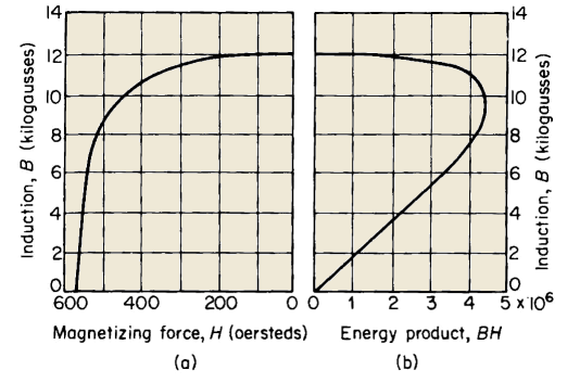
It is generally the aim of designers, unless other considerations such as available space or configuration are prohibitive, to design the magnet with its air gap such that the energy product is a maximum. It is evident that if the length of air gap were zero then the point P in Fig. 3-30 would coincide with the point Br and H would be zero and, of course, the energy product would be zero as well. If, on the other hand, the air gap were made very large, then the value of B would become accordingly low, resulting in a correspondingly low energy product. A typical demagnetization curve and the corresponding energy product curve for Alnico V are shown in Fig. 3-32. In that figure the flux density B is expressed in kilogausses (kilolines or kilomaxwells per square centimeter) and the magnetizing force H is expressed in oerstedts (4π/10 Ni per centimeter). These units are generally used in connection with the design of permanent magnets and are included in this textbook for that reason. The maximum energy product occurs at about B = 9.3 kilogausses and has a value of approximately 4.4 x 10⁶. If the effects of leakage are neglected, the relationship between the size of the magnet and that of the air gap is obtained from Eq. 3-85 and found to be
The volume Volm of the magnet is a minimum for a given air gap volume when the energy product BH is a maximum. Unless the length of the air gap is very small in relation to the length of the magnet there will be appreciable leakage, and a correction factor F is applied. The value of F lies in a range of from about 2 to 15. The length
of the air gap may not be uniform and the simple corrections for fringing discussed in Section 3-11 are not applicable. A factor f ranging from a value of 1.1 to about 1.5 is therefore applied. When these factors are applied the expression for the volume of the magnet is
The precise evaluation of the constants F and f is not straightforward, and requires judgment based on experience as well as on a thorough understanding of the application in which the magnet is put to use. The leakage may be minimized by locating the air gap in the magnet as shown in Fig. 3-33(a). With such an arrangement the mmf across the leakage path is due to the relatively low reluctance of the iron pieces. This situation corresponds to placing the exciting winding in an electromagnet over the leg of the core that contains the air gap. Figure 3-33(b) shows an arrangement in which the air gap is located in the iron pieces and which therefore makes for high leakage. The high mmf across the leakage path in this case is substantially equal to that across the air gap. The flux in the air gap of the structure in Fig. 3-33(a) would be considerably lower than that in the air gap of arrangement in Fig. 3-33(b) for the same size structure.
|
|||||||||||||||
Home  Magnetic Circuits Magnetic Circuits  Energy Product Energy Product |
|||||||||||||||
Last Update: 2011-02-16


