| Electronic Transformers and Circuits is a free introductory textbook on transformers and related circuits. See the editorial for more information.... |

|

Home  Pulse Circuits Pulse Circuits  Charging Reactors Charging Reactors |
||||||||


|
||||||||
Charging Reactors
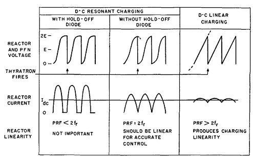
When no hold-off diode is used, both reactor inductance and PRF must be held to close tolerances, to maintain high voltage across PFN, with resonant frequency fr exactly equal to PRF/2. Linearity of inductance with change in direct current is also necessary for accurate control. Reactors designed by Fig. 71, p. 100, are usually linear enough for the purpose. If fr < PRF/2 the hydrogen thyratron fires before voltage across PFN reaches its peak, but after steady-state conditions obtain this voltage nearly equals 2E. If fr is low enough, the increase of voltage is approximately linear with time. This result is called linear charging. Reactor inductance is large in this case, and charging current flows continuously. Here also a range of PRF's may be used, all greater than 2fr Reactor voltages and currents for the three methods of charging are illustrated by Fig. 256.
In all cases, Q should be high (more than 10) for efficient pulser operation. Voltages in Fig. 256 are for infinite Q. Voltage is shown for the reactor terminal that connects to PFN. With a hold-off diode, this voltage appears on both terminals during the intervals when current is zero. Without the diode, or if diode and reactor in Fig. 252 are interchanged, the voltage at the left-hand terminal, Fig. 252, is E. Insulation may then be graded accordingly. In all cases, peak voltage across the reactor is E. A-c flux density may be calculated as in a filter reactor, but the effective frequency is 2fr because the flux excursion is in one direction only at frequency fr. In a-c resonant charging, reactor voltage would increase to QE, where E is the a-c input voltage, if charging continued for a sufficient number of cycles. If reactor Q > 10 and the thyratron is fired at the end of one full charging cycle, maximum PFN voltage is πEpk, where Epk is the peak value of applied a-c voltage. In a-c charging the supply transformer inductance may be used instead of a separate reactor and results in somewhat less total weight. A high reactance transformer is useful for this purpose, with shunts as in Current-Limiting Transformers. If a hold-off diode is used with a-c charging, an ordinary plate transformer may be used and weight reduced still further.(1)
|
||||||||
Home  Pulse Circuits Pulse Circuits  Charging Reactors Charging Reactors |
||||||||
Last Update: 2011-02-17


