| Electronic Transformers and Circuits is a free introductory textbook on transformers and related circuits. See the editorial for more information.... |

|

Home  Pulse and Video Transformers Pulse and Video Transformers  Front-Edge Response Front-Edge Response |
||||||||||||


|
||||||||||||
Front-Edge Response
The step-up transformer is illustrated by Fig. 229.
When the front of the wave (Fig. 226) is suddenly impressed on the transformer, it is simulated by the closing of switch S. At this initial instant, voltage e across R2 is zero, and the current from battery E is also zero. This furnishes two initial conditions for equation 128, which expresses the rate of rise of voltage e from zero to its final steady value Ea = ER2/(R1 + R2):
where m1, m2 = -m(1 ±
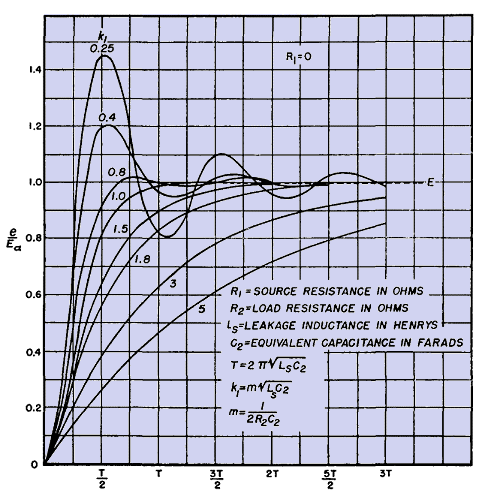
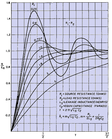
Figure 230 shows the rate of rise of the transformed pulse for R1 = 0 and Fig. 231 for R1 = R2. In hard-tube modulators, source resistance is comparatively small and approaches R1 = 0. Line-type modulators are usually designed so that R1 = R2. The scale of abscissas for these curves is not time but percentage of the time constant T of the transformer. The equation for this time constant is given in Figs. 230 and 231.
The greater the transformer leakage inductance and distributed capacitance, the slower is the rate of rise, although the effect of R1 and R2 is important, for they affect the damping factor k1. If a slight amount ofoscillation can be tolerated, the wave rises up faster than if no oscillation is present. Yet, if the circuit is damped very little, the oscillation may reach a maximum initial voltage of twice steady-state voltage Ea, and usually such high peaks are objectionable. The values for k1 given in these figures are those which fall within the most practicable range. Time required for pulse voltage to reach 90 per cent of Ea is given in Fig. 232.
|
||||||||||||
Home  Pulse and Video Transformers Pulse and Video Transformers  Front-Edge Response Front-Edge Response |
||||||||||||
Last Update: 2011-01-24


 ).
).


