| Electronic Transformers and Circuits is a free introductory textbook on transformers and related circuits. See the editorial for more information.... |

|

Home  Higher-Frequency Transformers Higher-Frequency Transformers  Iron-Core Transformers Iron-Core Transformers |
||||||||||||||||


|
||||||||||||||||
Iron-Core Transformers
In carrier frequency transmitters, transformers are normally used for coupling between stages and for coupling the output stage to the line. They sometimes transform a large amount of carrier power. Coils are usually wound in single layers, spaced well apart to reduce capacitance, and have but few turns. If the necessary turns cannot be wound in a single layer, a bank winding like that shown in Fig. 159 may be used.
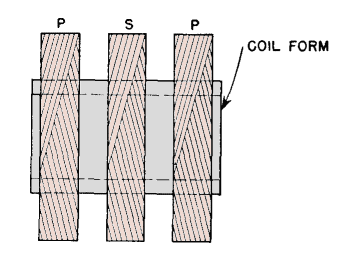
This winding has more capacitance than a single layer but much less than two layers wound in the ordinary way. Since intrawinding layer-to-layer capacitance is zero in these transformers, the resonance frequency fr is usually determined by winding-to-winding capacitance. In high impedance circuits, the winding-to-winding capacitance may be reduced by winding "pies" or self-supporting vertical sections side by side. Pies are wound with one or more throws per turn and may be several turns wide. They have the general appearance of Fig. 160.(1)
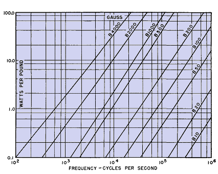
High, narrow core windows or several pies are desirable to reduce leakage inductance. Transformer loss is mostly core loss. Two-mil grain-oriented steel can be used advantageously in such transformers, because of its low losses and high permeability. In transmitter operation, class AB or class B amplifiers are commonly used, with or without modulation, which may be as high as 100 per cent. In a receiver, input and interstage transformers also are employed, mainly to obtain voltage gain or for isolation purposes. Similar transformers are used for line matching, especially where overhead lines are connected to underground cables. Line impedance changes abruptly, and transformers may be necessary for good power transfer. Core data at these frequencies are usually not available except for a limited choice of materials and gages. Approximate loss for 2-mil oriented steel is given in Fig. 161.
Interpolation or extrapolation from known data may be necessary to estimate core losses. In spite of this limitation, carrier frequency transformers are widely used. Some of the transformers in Fig. 16 operate in the carrier band. Core steel permeability decreases at high frequencies, depending on the lamination thickness. Oriented steel and nickel alloys have high permeability at low frequencies, but, unless thin laminations are used, this advantage disappears at frequencies of 20 to 50 kc. The approximate decline for low induction is shown in Fig. 162.
Decrease of permeability may be so rapid that OCL nearly decreases inversely as frequency with 0.014-in. and even 0.005-in. material.(2) Grain-oriented steel 0.002 in. thick is well suited to these frequencies. Transformers are used at still higher frequencies. Capacitance limits the upper frequency at which amplifier transformers may be operated. In a tuned circuit amplifier, the tuning includes the incidental and tube capacitance as well as the tank circuit capacitance. A transformer has no tuning to compensate for such capacitances. Even with zero winding capacitance there would be a frequency limit at which any tube could operate into an untuned transformer without spoiling its efficiency or other characteristics. The most favorable condition for the use of transformers at higher frequencies is low circuit impedance. With low leakage inductance and low impedance circuits, transformer operation is possible in the high- and very-high-frequency bands.
|
||||||||||||||||
Home  Higher-Frequency Transformers Higher-Frequency Transformers  Iron-Core Transformers Iron-Core Transformers |
||||||||||||||||
Last Update: 2011-02-17


