| Electronic Transformers and Circuits is a free introductory textbook on transformers and related circuits. See the editorial for more information.... |

|

Home  Amplifier Transformers Amplifier Transformers  Push-Pull Amplifier Transformers Push-Pull Amplifier Transformers |
||||||||||||||


|
||||||||||||||
Push-Pull Amplifier Transformers
The analysis of single-side amplifiers in Section 67 applies to class A push-pull, except that the second-harmonic components in the amplifier output are due to unlike tubes rather than to low-impedance distortion.
Usually the decline with frequency response is greater for class B than for class A amplifiers, because the effect of internal plate impedance is greater. In the extreme, frequency response falls off proportionately with load impedance. A change in mode of operation occurs in a class B amplifier as the output passes from one tube to the other in the region of cut-off. This change-over may cause transient voltages in the amplifier which distort the output voltage wave form. If the two halves of the transformer primary winding are not tightly coupled, primary-to-primary leakage inductance causes nicks in the output voltage wave, in somewhat the same way as leakage inductance in a rectifier plate transformer. In a class B amplifier, the change from one tube to the other is less abrupt than in a rectifier, but in triode amplifiers perceptible nicks in the voltage wave occur if the ratio of primary-to-primary leakage reactance to average plate resistance is 4 or more.(1) Balanced operation in a push-pull amplifier, i.e., equal plate current and voltage swing on both sides, is possible only if the tubes are alike and if transformer winding turns and resistances per side are equal. Shell-type concentric windings do not fulfill this condition because the half of the primary nearer to the core tongue has lower resistance than the other half. Balance is easier to achieve in the core type of arrangement shown in Fig. 121.
In class A amplifiers close primary-primary coupling is not essential, and balance may be attained by arranging part coils as in Fig. 122.
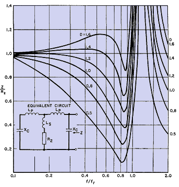
Because only half of the primary winding of a class B amplifier carries current during a half-cycle, the leakage flux and therefore the primary-to-secondary leakage inductance have approximately half the values with both windings active all the time. With capacitive currents, both windings are active, at least partially. Transformers with D > 1.0 have low capacitive currents, low leakage inductance, high resonance frequency, and extended frequency range, in addition to the load-impedance advantages given in Harmonic Distortion. At high frequencies a class B amplifier transformer presents a circuit to the tubes like that in Fig. 123.
Let L1 be leakage inductance between the halves of the primary winding, and L2 between each half of the primary and the secondary. L1 is the inductance of one half of the primary winding, measured with the other half-primary short-circuited and the secondary open. L2 is the inductance of one half of the primary winding, measured with the other half-primary open and the secondary short-circuited. In Fig. 123, L1 = 2LP and L2 = LP + Ls. Resonant frequency fr is determined by Xc and XL1 - 2πfL1. In this figure D = Xc/R2 at fr. First one tube delivers power into the equivalent circuit at one end; then, during the next half-cycle, this tube is cut off and the other tube delivers power into the circuit at the other end. Thus the transformer equivalent impedance Z seen looking into the circuit, first at the end shown and then at the other end, is fed by one of the tubes at all times. Impedance ratio Z/R2 varies with frequency as in Fig. 123. For some values of parameter D, impedance falls more rapidly than for class A amplifiers (Fig. 119), but frequency fr in Fig. 123 is determined by L and C having approximately half the values of these elements in class A amplifiers. Hence class B impedance stays flat at higher frequencies, although response may droop at lower frequencies, than for class A. Figure 123 is drawn for a ratio of L1/L2 = 1.5, which is a practical design ratio. Lower ratio L1/L2 results in deeper valleys in the impedance curve; higher L1/L2 is more likely to cause nicks in the voltage wave. Good practice consists in designing class B amplifier transformers so that the highest operating frequency is less than fr/2 and L1/L2 ≤ 1.5. Then harmonic distortion at high frequencies should not exceed 5 per cent.(2) Class B modulation transformer impedance is influenced by circuit elements, so that maintenance of constant impedance over a wide frequency band becomes an overall amplifier problem. This is discussed further in Amplifier Circuits - Introduction. Capacitive currents also cause unbalance at high frequencies, even with winding arrangements like Figs. 121 and 122. This is evident if the secondary winding in these figures is grounded at one end; the effective capacitances to the two primary windings are then unequal. This problem may be solved by keeping the capacitances small with liberal spacing, but this practice increases leakage inductance and cannot be carried very far. Coil mean turn length should be kept as small as possible by the use of the most suitable core steel. Core-type designs have smaller mean turns than shell-type. Also, the two outer coil sections have low capacitance to each other and to the case if liberal spacing is used, without an increase in leakage inductance. Flux in the space between the outer sections links all the windings on one leg and hence is not leakage flux. Consequently, this space is not part of the term a in equation 33. In push-pull amplifiers the winding arrangement of Fig. 121 is advantageous because of the low capacitance between the points of greatest potential difference, A and C.
|
||||||||||||||
Home  Amplifier Transformers Amplifier Transformers  Push-Pull Amplifier Transformers Push-Pull Amplifier Transformers |
||||||||||||||
Last Update: 2011-02-17


