| Electronic Transformers and Circuits is a free introductory textbook on transformers and related circuits. See the editorial for more information.... |

|

Home  Transformer Construction, Materials, and Ratings Transformer Construction, Materials, and Ratings  Dielectric Strength Dielectric Strength |
||||||||||
| See also: Creepage Distance | ||||||||||


|
||||||||||
Dielectric Strength
Differences in hearing ability between persons make a corona measurement desirable. This is done by means of the standard NEMA circuit of Fig. 38.(1)
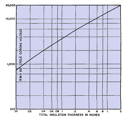
With the transformer connected as shown, receiver output meter is adjusted to half-scale by a volume control potentiometer in the receiver. Next, the transformer is replaced by a modulated 1-mc signal generator, the output of which is varied until the noise meter output is again half-scale. The signal generator output in microvolts is read on an attenuator; this is then a measurement of the corona present. Class B insulation can be worked much closer to the ultimate dielectric strength, but the latter is less a factor in determining size than creepage distance to the core. For mica an approximate working voltage rule is 100 volts rms per mil thickness. Insulated coils in air are subject to a two-dielectric effect that is peculiarly troublesome. If the path of electric stress is partly through solid material and partly through air, the air may be overstressed because it has the lower dielectric constant (unity, compared with 3 to 5 for most coil materials). If this condition exists, it is usually impracticable to increase the air distance and so reduce the volts per inch to a value below the corona limit. The addition of more solid insulation over the whole coil may make it too large. Often the only feasible remedy is to fill the air space with more solid material, either in the form of filling compound or strips of insulation like micarta or press-board. It is important, when dealing with insulation voltage, to make a distinction between test voltage and operating voltage. Of the two, operating voltage is the better value to specify.
|
||||||||||
Home  Transformer Construction, Materials, and Ratings Transformer Construction, Materials, and Ratings  Dielectric Strength Dielectric Strength |
||||||||||
Last Update: 2011-02-17


