| Basic Radio is a free introductory textbook on electronics based on tubes. See the editorial for more information.... |

|

Home  Microwaves Microwaves  Positive-Grid Oscillators Positive-Grid Oscillators |
|||||||||


|
|||||||||
|
Positive-Grid OscillatorsAuthor: J.B. Hoag
An explanation of the processes whereby the oscillating electrons extract energy from the batteries and deliver it to associated high frequency circuits is not at all easy to give. The exact mathematical treatment is very complicated and does not assist greatly in the practical operation of the oscillators. Suffice it to say that, due to the pendulations of the electrons back and forth about the grid, high frequency oscillations are produced in a tuned circuit connected across the grid and the plate. A circuit of this type is shown in Fig. 38 A.
The period of the oscillations which are generated is equal to the time taken by the electrons for one complete excursion inside the tube. Because the electrons travel very fast, this time is exceedingly small; hence the frequency of the radio waves is very high. The resonant circuits should, therefore, be of the linear-circuit type, as shown in Fig. 38 A. The intensity of the oscillations can be increased by using a double-ended tube, as in Fig. 38 B, where there are two wires from the plate and two from the grid. These are taken out on opposite sides of the glass envelope.
Peculiar non-harmonic oscillations are sometimes generated in B-K tubes. They have been found to be due to parasitic oscillations whose frequencies correspond to the natural electrical periods of the electrode structures inside the tubes, such as the filament lead wires and so on. These are, generally, of comparatively long wave-lengths. The wave-lengths radiated from these oscillators are very short, ranging from a few meters down to approximately 10 cms. If the grid is equidistant from the filament and plate, and if the plate is at the same potential as the filament, then the following simple equation can be used to predict the wave-length λ (cms.) of the oscillations:
where D is the inside diameter of the cylindrical plate, in cms., and Eg is the potential of the grid, in volts. Referring now to Fig. 38 A, let us measure the wave-length produced as the condenser across the two parallel wires is moved outward from the tube.
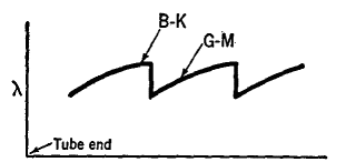
The curve in Fig. 38 C shows that for a short distance, marked B-K, the wave-length generated is independent of the external tuning circuit. Suddenly, however, the wave-length drops to a smaller value, after which it rises along a line, marked G-M, to its former value. In the G-M condition, the external circuit obviously influences the oscillations inside the tube so that they take place differently than they did by the pure B-K method. This operating condition was first discovered in 1922 by Gill and Morell (hence the initials G-M). It is found in practice that the G-M oscillations are not only shorter than the B-K type but also are very much more intense. Their wave-length, however, is subject to changes in the external system, whereas the B-K oscillations are determined exclusively by the voltages upon the given tube.
|
|||||||||
Home  Microwaves Microwaves  Positive-Grid Oscillators Positive-Grid Oscillators |
|||||||||
Last Update: 2010-11-27


