| Basic Radio is a free introductory textbook on electronics based on tubes. See the editorial for more information.... |

|

Home  Transmission of Signals Transmission of Signals  Short-Lines Short-Lines  Linear-Circuits Linear-Circuits |
||||||||||||||||||||


|
||||||||||||||||||||
|
Linear-CircuitsAuthor: J.B. Hoag A linear-circuit can be made of two short parallel wires or of a section of coaxial line, whose length is approximately one-quarter, one-half, etc., the wave-length of the radio waves with which it is resonant. The physical appearance is so simple that one can easily miss the necessary fundamental principles involved in its design. What we need is a system of conductors which:
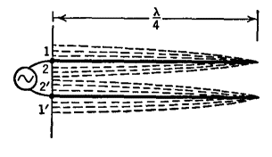
Note that the currents are greatest where the voltages are least, and vice versa. Also note that the currents and voltages at all points along one of the wires are out-of-phase with the corresponding values along the other wire. As time goes on, the current in each wire at the input end passes from the maximum value shown in Fig. 36 A to zero, to a reversed maximum, and back again during each cycle of the oscillator.
As shown in Fig. 36 B: at the start, the currents are 1 and 1' in the two wires; at the half-cycle they are 2 and 2' and are still out-of-phase with each other. Finally, therefore, the currents in a quarter-wave resonant line are out-of-phase with each other not only at every point along the line but also at every instant. Under these conditions, the magnetic and electric fields surrounding the two conductors are always in opposing directions and the radiation from the system is kept to a minimum. The desirable condition of standing-waves can be produced with short-lines which are any multiple of one-quarter wave-length long. One may start with a line of fixed length and vary the frequency of the oscillator to find these " modes of vibration," or one may use a generator of fixed frequency and change the length of the line. Figures 36 C and 36 D illustrate these two possibilities.
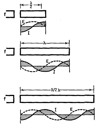
In Fig. 36 C, the frequency of the source is supposed to be steadily increased; or the wave-length is decreased. When the length of the wave (λ) is twice that of the line (l), the fundamental or first-harmonic mode of vibration is attained. With the ends of the line shorted, as shown, the voltage at these points is always zero, as indicated by the dotted (E) line. As the wavelength is further shortened, a second harmonic standing-wave will be produced when the line and the wave are of the same length. Then, too, the voltages at the ends will be zero, whereas the currents will have maximum value.
Figure 36 D shows a " trombone " line, whose length can be progressively increased, while the frequency (f) of the source remains fixed. The first three harmonic or resonant conditions are shown in the figure. The physical length of a short-line is never exactly equal to one-quarter (or a multiple of λ/4) because of end-effects and because the waves do not travel along the wires as fast as they do in free space. The effect of the velocity retardation has been discussed in the chapter on Long-Lines. For a quarter-wave line, n = λ'/4, so that, if the electrical length is l' and the physical length is l, we have l' = (246/f) (v/c) = l (v/c), where f is the frequency in MHz and the ratio (v/c) has the following approximate values: for parallel wires, 0.975; air-insulated concentric lines, 0.85; rubber-insulated concentric and twisted pair, 0.60. The end-effects can be understood by referring to Fig. 36 E.
A voltage induced at point P must travel along the end-shorting-bar before reaching the line itself. There is, then, a correction equal to one-half the separation of the wires. Even this is not an exact statement, for the bends in the wire distort the field from what it would have been along a straight wire. We can only say that at a short-circuited end, the correction is approximately equal to one-half the line spacing. Similarly, a correction is needed at the open end. If a condenser is fastened across the open end, the correction can become comparatively large. When the wires are farther apart, the closed-end corrections become larger, but the velocity of propagation along the wires becomes more nearly that of light; hence the equation and numerical values given above serve well for practical purposes for lines of the type shown in Fig. 36 E. In order to keep the radiation to as small a value as possible, the parallel wires should not be farther apart, center to center, than 10 per cent of the wave-length. Also, they must not be placed too close together in comparison with their diameter, for the following reason: The h.f. currents are confined to the skin of the conductors; their penetration is only one one-thousandth of a millimeter at the ultra-high frequencies (λ = 10 m. or less). See Fig. 36 F.
The fields of these currents extend throughout the space, not only around the outside of the wires, but also inside the conducting layer. Outside, there may be only small conduction or dielectric losses in the insulation (air), but inside, the fluctuating magnetic fields set up eddy currents which absorb energy from the line and dissipate it in the form of heat. One obvious solution to this difficulty is to use hollow tubes. In practice, at the ultra-high frequencies, large copper tubes are used. They offer large surface area (low ohmic losses), small internal losses, and desirable rigidity for stabilization of the line (both mechanical and electrical). In order to reduce the radiation of energy from parallel wires, they can be enclosed in a metal shield, as in Fig. 36 G.
Then the electric field of the line does not affect neighboring circuits; nor do external fluctuating electric fields affect it. But the eddy currents set up in the shield cause losses from the line; the more so the closer the shield is to the line. The problem of shielding has been solved much more elegantly by the use of concentric-lines, as in Fig. 36 H.
The central metal rod is one wire and the hollow metal tube is the other " wire." Between the two, a standing-wave of electric and magnetic fields is set up. Energy in this field which tries to radiate away is absorbed in the outer cylinder; the eddy currents produce fields back into the inside of the line. In other words, radiation losses are greatly reduced. Of course, the eddy currents suffer ohmic losses, but only on the large inner surface of the outer cylinder. The total loss in concentric cable is appreciably less than in a corresponding length of open, parallel wire line. Another way of saying the same thing is that the Q of a concentric line is very high, as much as 15,000 or more. Suppose we have a line which is one half-wave long, or any integral— multiple of a half-wave in length. Then the impedance, as measured at the input end, will be equal to the impedance connected to its output end. With a condenser at the output, whose reactance is given by 1/2πfC, the system will act capacitatively on the load, and with a value equal to 1/2πfC ohms. With an inductance at the output, the system will have an inductive reactance of an amount given by 2πfC. With a pure resistance load (R), the input impedance will equal R ohms. With a resonant LCR load, the input impedance will be a pure resistance equal to R, because the capacitive and inductive reactances cancel each other. In other words, a half-wave line acts like a one-to-one transformer. With a line which is one-quarter of a wave long, or any odd multiple of a quarter-wave, the input impedance Zi is given by Zi = Zc2/Zt, where Zc is the characteristic impedance of the line and Zt is the output impedance. The line acts, therefore, as an impedance-transformer for coupling a source of one impedance to a load of a different impedance. By introducing the source or the load at various suitable points along the line, as in Fig. 36 I, adjustments can be made so as to match the impedance of the source or the load.
In these cases, the impedances, looking into the line in either direction from the selected point, are equal to each other. In Fig. 36 I, the left circuit is sometimes used to feed an antenna (the load). The right circuit has been used to produce high output end-voltages in a cyclotron (the " dees " are at the output end). In this case, tapping the fixed voltage of the source onto the line at (b) gives a voltage distribution (B). Moving the tap closer to the shorted end, the same voltage source results in the distribution shown at (A) and hence gives much higher voltages at the open end.
|
||||||||||||||||||||
Home  Transmission of Signals Transmission of Signals  Short-Lines Short-Lines  Linear-Circuits Linear-Circuits |
||||||||||||||||||||
Last Update: 2010-11-27


