| Basic Radio is a free introductory textbook on electronics based on tubes. See the editorial for more information.... |

|

Home  Electronic Devices Electronic Devices  Gas-Filled Tubes Gas-Filled Tubes  Gas-filled Triodes Gas-filled Triodes |
||||||||


|
||||||||
|
Gas-filled TriodesAuthor: J.B. Hoag These are known by the commercial trade names of "thyratron", meaning "door", and "grid-glow" tubes. Their action is quite different from that of high-vacuum triodes, because the grid serves to start an arc discharge between the cathode and the plate, and then loses its ability to affect the magnitude of the plate current. In order to stop the plate current it is necessary to reduce its voltage to zero.1 Inasmuch as the grid acts only like a trigger to start the plate current, the tubes are comparable in application to lock-in-relays, wherein a small amount of power is used to turn on comparatively large currents from a local source.
It is possible, in the following way, to understand how the grid can start the plate current and then cease to function. Suppose that the grid is quite negative at the start. When the plate voltage is first connected, electrons from the hot cathode create positive ions and electrons by bombardment of the atoms near the grid. The electrons are repelled at great speed from the grid, which is negative, whereas the positive ions are drawn toward it much more slowly, because they are comparatively heavy. The electrons will have moved away from the region around the grid while the positive ions are slowly moving toward their destination. Thus a positive ion sheath is formed around the grid wires. With a highly negative grid these sheaths will be sufficiently large to overlap each other and prevent the current flow to the plate. If, now, the grid is made less and less negative, the sheaths become thinner and thinner until, at a critical value of the grid voltage called the striking potential, Ec, they no longer close the largest hole in the grid structure. The electric field on the plate is no longer able to attract electrons from the region between the cathode and the grid. A current then flows through the plate circuit. Once the current has started, the sheaths all become very small and, although subject to small changes in size when the grid voltage is changed, they cannot be made sufficiently large to stop the plate current. It requires a reduction of the plate voltage to zero before the current is shut off.
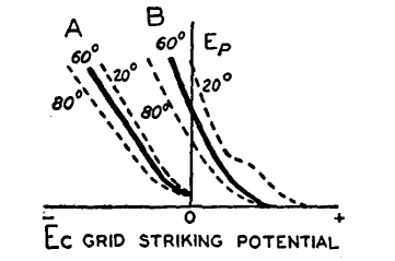
The striking potential of the tube depends on the plate potential, EP, as shown in Fig. 18 G. Any one of the curves in this figure shows the value of the grid potential for a given plate potential which will just start the flow of current through the tube. The curve shows simultaneous values of plate and striking potentials, in contradistinction to the usual graphs which show how one quantity y depends upon another quantity x. In Fig. 18 G, curve A is typical of the so-called negatively-controlled tube; B is for the positively-controlled type of tube. In the latter case, the striking voltage is affected by the formation of negative charges on the inner surfaces of the glass walls of the tube. The smaller tubes, which handle smaller currents and are operated at lower voltages, contain a rare gas such as argon whose pressure is unaffected by temperature. The larger, more powerful tubes which operate at potentials above a few hundred volts contain mercury whose vapor pressure varies from 0.001 to 0.1 mm., the higher pressures for the higher temperatures. As shown in Fig. 18 G, by the dotted lines, these pressure changes alter the striking potential. The striking curves of different tubes are not always as straight as those of Fig. 18 G. When, however, they are straight, their slope serves as a useful constant of the tube. Thus the grid-control ratio p is defined as the ratio of the plate voltage Ep to the striking potential Ec. The larger this number the more readily will a small change of grid voltage trip the tube and start the plate current flowing. A word of precaution is necessary for the practical operation of this class of tube. The filament must be heated up to its normal operating temperature before the plate voltage is applied and, second, the plate voltage must be removed from the tube before the filament is allowed to cool down. Otherwise the high voltage drop across the tube will exceed the disintegration voltage and the emitting surface will be destroyed. On the other hand, when the filament is hot and a discharge is started, the voltage drop across the tube comes almost instantly to the safe, fixed value of 10 to 20 volts, depending on the pressure in the tube and its structure.
|
||||||||
Home  Electronic Devices Electronic Devices  Gas-Filled Tubes Gas-Filled Tubes  Gas-filled Triodes Gas-filled Triodes |
||||||||
Last Update: 2010-11-21


