| Basic Radio is a free introductory textbook on electronics based on tubes. See the editorial for more information.... |

|

Home  Basic Circuits Basic Circuits  Some Simple Oscillators Some Simple Oscillators  A Tickler Circuit Oscillator A Tickler Circuit Oscillator |
|||||


|
|||||
|
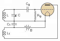
A Tickler Circuit OscillatorAuthor: J.B. Hoag In the chapter on amplifiers we have seen that the amplified current in the plate circuit of a three-electrode tube can be fed back to the grid circuit by means of a tickler coil, with resultant increase in the amplification of the signal. If the tickler coil is moved closer and closer to the grid coil, the amplification increases until, at a critical value of " coupling " between the two coils, the tube will produce oscillations within itself, without the aid of an input signal. In order that a tube shall be self-oscillating, two main conditions must be satisfied. First, it is necessary that the power transferred from the plate circuit to the grid circuit shall be equal to or greater than the circuit losses. Second, it is necessary that the feedback be positive or regenerative.
Figure 14 A shows a simple tickler circuit. When the B-battery is first connected, small random variations — no matter how minute — are rapidly amplified to such a point as to start the tube in oscillation.
The frequency of the oscillations will be nearly equal to the resonant frequency of the LC or tank circuit, as given by the equation
In general, the oscillation frequency will be governed by that circuit in which the losses are least, i.e., by the LC circuit which has the highest Q.
|
|||||
Home  Basic Circuits Basic Circuits  Some Simple Oscillators Some Simple Oscillators  A Tickler Circuit Oscillator A Tickler Circuit Oscillator |
|||||
Last Update: 2009-11-01


