| Basic Radio is a free introductory textbook on electronics based on tubes. See the editorial for more information.... |

|

Home  Electronic Devices Electronic Devices  Triodes Triodes  The Plate Resistance The Plate Resistance |
|||||||


|
|||||||
|
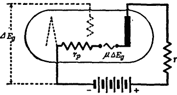
The Plate ResistanceAuthor: J.B. Hoag The opposition to the flow of electrons between the filament and the plate set up by the space charge and by the negatively charged grid is the equivalent of a resistance rP, known as the plate resistance of the tube. A law, similar to that of Ohm, can be written for the case of a three-electrode tube. There is, however, a sharp difference between Ohm's law and the new law, in that the new one uses changes in current and changes in voltage rather than the currents and voltages themselves. Thus, the change of plate current ip is given by the change of plate voltage (μeg) divided by the total resistance of the circuit (r + rp).
As shown in Fig. 12 E this leads to the equation
where r is the external or load resistance and rp is the internal resistance (or plate "impedance") of the tube, defined for zero load by the equation
We can better understand the meaning of the plate resistance of a tube by referring to Fig. 12 F which shows the plate current dependence on the plate voltage. Since this curve is not a straight line, rp varies as the voltage of the plate changes. With a fixed voltage on the plate, rp is a constant. Note that the d.c. resistance of the tube is given by Ep/Ip whereas rp = ep/ip. The values, of the plate impedance rp for normal operating voltages of different commercial triodes range from 800 to 150,000 ohms. They can be obtained from the curves of the tube, by means of tube testers, and from data published by the manufacturer of the tube.
|
|||||||
Home  Electronic Devices Electronic Devices  Triodes Triodes  The Plate Resistance The Plate Resistance |
|||||||
Last Update: 2009-11-01


