| Electrical Communication is a free textbook on the basics of communication technology. See the editorial for more information.... |

|
Home  Electronic Applications in Communication Oscillators Cavity Oscillators Electronic Applications in Communication Oscillators Cavity Oscillators |
|||


|
  |
||
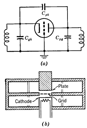
Cavity OscillatorsA cavity of the general shape to be discussed in this section is, in a sense, composed of many parallel sections of transmission lines that are combined into one metallic structure. At certain frequencies, therefore, the input impedance at the opening of a metallic cavity is pure inductive reactance. The simplified circuit of a triode oscillator with grounded grid and tuning in both the cathode and plate circuits is shown in Fig. 39a. Feedback for sustaining oscillations is through the plate to cathode capacitance. A cavity-type oscillator is shown in Fig. 396. The electronic portion and the cavity portion are in reality part of the same tube structure. The relationship between the two circuits of Figs. 39a and 396 is evident. The cavities provide the inductances, and the electrodes provide the capacitances, giving an oscillator that will generate frequencies of thousands of megacycles.31,32,33
A vacuum tube, called a disk-seal tube31 or lighthouse tube, is constructed with parallel closely spaced "disk" electrodes such as are shown in Fig. 39b. The close spacing reduces the transit time, or time required for the electrons to pass from the cathode to the plate. This makes possible high-frequency oscillations. If the transit time is not short and if the frequency is high, an electron may start out toward the plate, only to arrive there under unfavorable phase conditions. Although the preceding discussion is for the use of disk-seal tubes as oscillators, they are also used at ultrahigh frequencies for amplification and for other purposes, much like ordinary vacuum tubes.34,35
|
|||
| Home Electronic Applications in Communication Oscillators Cavity Oscillators |
|
||
Last Update: 2011-05-30