| Electrical Communication is a free textbook on the basics of communication technology. See the editorial for more information.... |

|

Home  Electric Networks Electric Networks  Network Theorems Network Theorems |
|||||||


|
|||||||
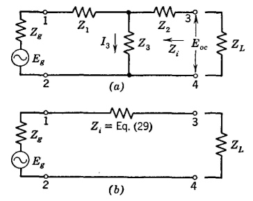
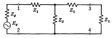
Network TheoremsThe theorems now to be discussed are useful in studying networks. It is assumed that the networks are composed of elements that are linear and bilateral, that the steady-state condition has been reached, and that all quantities are complex. Thévenin's Theorem. If an impedance ZL is connected between any two points of a circuit, the current IL that will flow through this impedance is the same as if the impedance ZL is connected to a generator whose constant generated voltage Eg is the same as the voltage Eoc between the two points of the circuit, prior to the connection, and whose internal impedance Zg is the same as the impedance Zi measured, prior to the connection, back into the circuit, with each source of driving voltage within the circuit replaced with an impedance equal in value to the internal impedance of that source. To prove Thévenin's theorem, recall that any passive network can be represented by the T section of Fig. 12. If a generator is connected as shown, an open-circuit voltage will appear between terminals 3-4. The magnitude of this open-circuit voltage is
The impedance measured toward the generator from terminals 3-4 is
According to Thevenin's theorem, when ZL is connected
From ordinary circuit theory, when ZL is connected,
Since the voltage drops across Z3 and (Z2 + ZL) of Fig. 12 must be equal,
Substituting equation 31 in equation 32 gives
Thus, since equations 30 and 33 are identical, the proof of Thévenin's theorem is established. Regarding the last portion of Thévenin's theorem, consult the superposition theorem in the following pages. Norton's Theorem. If an impedance ZL is connected between any two points of a circuit, the current IL that will flow through this impedance is the same as if the impedance ZL is connected to a generator whose constant generated current Ig is the same as the current Isc that flows if the two points of the circuit are short circuited, the constant-current generator being in parallel with an impedance Zi measured prior to the connection back into the circuit, with each other source of driving voltage within the circuit replaced with an impedance equal in value to the internal impedance of that source. In proving Norton's theorem, it will be recalled that any circuit can be reduced to the T network of Fig. 13 (a) and it must be shown that this circuit is equivalent to Fig. 13 (b). Since Fig. 13 (a) already has been shown to be equal to Fig. 12(b), if an equivalence between Fig. 12(b) (also reproduced as Fig. 13 (c)) and Fig. 13(b) is established, then Norton's theorem will be proved.
From Thévenin's theorem, the current that will flow through a load impedance ZL is
and, if the generator of Fig. 13 (c) is short-circuited,
According to Norton's theorem and the circuit of Fig. 13(6),
From equation 35, equation 36 becomes
which is the same as equation 34, thus establishing the fact that Norton's theorem and the circuit of Fig 13 (b) can be used in solving network problems. Norton's theorem is convenient for use with circuits of high impedance, such as voltage amplifiers employing tetrodes and pentodes having internal impedances (plate resistances) of about 1,000,000 ohms. Thévenin's theorem is convenient for low-impedance circuits. Superposition Theorem. If a network has more than one source of driving voltage, the current that flows at any point, or the voltage between any two points, is the sum of the currents or voltages at these points which would exist if each source of voltage were considered separately, each of the other sources being replaced at that time by an impedance equal to the internal impedance of that source.
If the impedances in a network are linear, and their values are not affected by the magnitudes of the currents and voltages existing, then the current or voltage in the various portions of the circuit are independent of each other and the principle of superposition applies. A simple laboratory experiment will verify this principle. This theorem can be applied to a circuit, and the use of the Kirchhoff's law method avoided. Also, the effect of a given generator voltage (of the same or different frequency) at a given point can be determined without considering the effects of other voltage sources. Reciprocity Theorem. If any source of voltage E located at one point in a network produces a current I at any other point in the network, the same source of voltage E placed at the second point will produce the same current I at the first point. Any complex network can be reduced to the simple T section of Fig. 14. The current IL, that generator Eg forces through impedance ZL is given by equation 33. If the source of voltage Eg only is removed and placed in series with ZL and if equations such as 31, 32, and 33 for the current Ig through Zg are written, it will be found that the two currents are identical. Compensation Theorem. Any impedance in an energized network may be replaced by a generator of zero internal impedance whose instantaneous generated voltage is equal to the instantaneous potential difference across the replaced impedance caused by the current flowing through the impedance. The principle on which this theorem is based is well known. Thus in Fig. 15, if the polarity of the instantaneous generated voltage used to replace the impedance as indicated and if the magnitude of this generated voltage equals the magnitude of the potential difference across the impedance, the currents in the two circuits will be identical. Maximum Power Transfer Theorems. If a passive network is joined to an active network by two terminals the power that will be absorbed by the passive network will be maximum if the impedances measured in the two directions, prior to the connection, are conjugates. This was considered on page 70, and additional discussion is unnecessary, except to point out that, since any network can be replaced by a simple T structure and because Thévenin's theorem applies, this theorem can be represented by Fig. 16. For maximum power transfer, if Zg = R+jX, then ZL should be ZL = R - jX, and vice versa. Conjugate impedances have equal resistances and equal but opposite reactances. If the magnitude, but not the angle, of a load impedance may be varied, then the maximum power will be absorbed when the magnitude of the load impedance equals the magnitude of the internal impedance of the source. This was considered on page 71, and additional discussion is unnecessary.
|
|||||||
Home  Electric Networks Electric Networks  Network Theorems Network Theorems |
|||||||
Last Update: 2011-05-30


